

Quick Answer: Sizing Series vs Parallel Solar Arrays for 150V MPPT
A 150V MPPT maximum voltage rating demands series-string configuration optimization using cold-weather Voc correction (NEC 690.7). Calculate panel string voltage at 25°C, apply negative temperature coefficient (~–0.3%/°C), verify winter peak Voc remains under 150V, then parallel multiple strings to achieve target amperage. Exceed this voltage ceiling and your controller fails catastrophically.

Pros
- 24 connector pairs listed
- Crimping tool included
- Wire stripper included
Cons
- Connector ratings and wire gauge range not supplied
- Compatibility with specific panels not stated in the record
A combined connector and tool kit for solar panel wiring, with 24 connector pairs plus a crimping tool and wire stripper. It suits DIY solar users who want the connectors and tools in one set, but the record does not list connector ratings, wire gauge range or panel compatibility, so verify these details before purchase and use.
- Kit contents: 24 pairs of solar panel connectors, crimping tool, wire stripper
- Product type: solar panel connector kit with tools, an accessory rather than a power device
- Connector ratings, wire gauge range and compatibility: not supplied
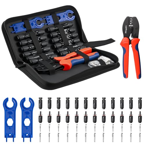
Pros
- Crimper tool included
- 12 connector pairs included
- Two spanners included
Cons
- Connector type and crimp specifications not supplied
- Compatibility with specific panels and wire not stated
A tool kit for crimping solar connectors, supplying a crimper, 12 connector pairs and 2 spanners in one set. It suits installers or DIY users who need connector and crimping tools together, but the record does not confirm connector type or crimp specifications, so check that the connectors match your panel and wire before use.
- Kit contents: crimper tool, 12 pairs of connectors, 2 spanners
- Product type: solar crimper tool kit, an accessory rather than a power device
- Connector type and crimp dimensions: not supplied
Root Cause Engineering & Mechanical Principles
MPPT (Maximum Power Point Tracking) controllers operate within strict voltage boundaries. A 150V-rated MPPT accepts solar arrays delivering 0–150 volts DC input. Unlike PWM controllers that simply switch battery voltage through panels, MPPT units dynamically adjust their internal DC-DC converter to extract maximum available power across changing atmospheric conditions. The critical engineering principle: as temperature drops, individual solar panel Voc (open circuit voltage) rises predictably—typically 0.3% per degree Celsius below standard test conditions (STC: 25°C, 1000 W/m²). For detailed technical setup and system integration, reference our analysis on charge power stations at level 2 ev chargers (2026).
When you wire panels in series, voltages add directly. A single 400W panel rated 40V at 25°C becomes approximately 50.4V at freezing conditions (0°C). Five panels in series = 252V cold Voc—catastrophic overvoltage for a 150V MPPT. Parallel configurations sum only current (amps), preserving voltage safety margins. The engineering trade-off: parallel wiring demands thicker gauge conductors and lower total system efficiency due to increased resistive losses. According to the IEEE Photovoltaic Standards Committee, proper array configuration prevents equipment failure and optimizes harvested energy across seasonal temperature extremes.
Mechanical thermal stress compounds the challenge. Aluminum junction boxes and copper busbars expand and contract with temperature swings. Loose connections develop micro-arcing. Silicone encapsulants degrade under UV + moisture cycling, creating moisture ingress paths that trigger internal arcing and eventual component failure. Series arrays operating near voltage limits experience accelerated insulation degradation due to ionization stress—a phenomenon called partial discharge initiated by minor manufacturing defects.
| Failure Mode | Root Cause | Diagnostic Test | Tolerance Window | Resolution Difficulty |
|---|---|---|---|---|
| MPPT controller burned input stage | Sustained Voc > 150V from undersized strings or cold-weather spikes | Digital multimeter DC voltage measurement, Voc test at 5 a.m. winter ambient | Max 148V measured (2V safety margin for transients) | Critical—full controller replacement required |
| Junction box arcing / internal tracking | High voltage stress on 600V-rated silicone under marginal insulation cracks | Visual inspection + megohm resistance tester (>1000 MΩ across terminals required) | Minimum 1000 MΩ phase-to-ground, 500 MΩ between adjacent connections | High—requires panel disassembly or replacement |
| Conductor corrosion / connection resistance rise | Series-string current concentration + moisture ingress accelerates galvanic corrosion | IR thermography (series junction 12°C above ambient = problem), contact resistance < 0.5 mΩ required | Connection temperature rise ≤ 10°C over ambient under full sun | Medium—requires weatherproofing seal reapplication |
| Parallel-string imbalance current | Mismatched panel Voc or degraded bypass diodes in one string | Individual string current measurement via 0.1Ω shunt, expected variance < ±5% | String current match within 3–5% under identical sun angle and temperature | Medium—requires isolation and diode testing or panel replacement |
| Undersized series string for 150V ceiling | Insufficient panel count to deliver rated watts at MPPT optimal point | Calculate string voltage = (Voc rated @ 25°C) × 1.35 (cold correction factor) | Cold Voc must be ≤ 145V to maintain 5V safety margin below 150V limit | Low if reconfig possible; high if array physically locked |
Step-by-Step Diagnostic & Calibration Procedure
Phase 1: Baseline Voltage Assessment & Temperature Profiling
Step 1.1 – Measure Reference Panel Specifications
Obtain the exact Voc (open circuit voltage) and Isc (short circuit current) from manufacturer datasheets for every panel model in your array. If panels are mixed brands or ages, document each separately. Note the test condition temperature explicitly—most rate 25°C STC. Record Vmp (voltage at maximum power point) and Imp (current at max power). For example, a common high-wattage panel specification: Voc = 39.8V, Vmp = 31.9V, Isc = 10.1A, Imp = 9.63A at 25°C, with Voc temperature coefficient = –0.29%/°C.
Step 1.2 – Calculate Cold-Weather Maximum Voc
Apply NEC Article 690.7 temperature correction. The formula: Cold Voc = Voc(rated) × [1 + (T(cold) – 25°C) × TempCoeff(Voc)]. For most climates, assume worst-case minimum outdoor ambient of –10°C (14°F). Using our example panel: Cold Voc = 39.8V × [1 + (–10 – 25) × (–0.0029)] = 39.8V × 1.102 = 43.85V per panel. For a five-panel series string: Cold string Voc = 43.85V × 5 = 219.25V. This exceeds 150V—configuration is impossible.
Now reduce series strings to three panels: Cold string Voc = 43.85V × 3 = 131.55V. This remains below 150V with an adequate safety margin.
Step 1.3 – Validate At-Temperature Voltage Measurement
Before installation commissioning, measure actual array Voc using a quality digital multimeter (minimum 4.5-digit accuracy, 600V DC range) on a clear morning when outdoor air temperature reaches local winter minimum. Set meter to DC voltage, connect across the entire series string with MPPT breaker open and all load disconnected. Record the measured value—it should fall within ±3% of calculated cold Voc. Deviation suggests shaded panels, connector corrosion, or degraded bypass diodes.
Phase 2: Series-Parallel Configuration Optimization
Step 2.1 – Determine Target Array Power (Watts)
Calculate required array power from your battery capacity and charge time target. For a 48V, 200Ah LiFePO₄ battery (9.6 kWh usable) with a 4-hour charge window under peak solar (1 kWh/m²/day winter, 4 peak equivalent hours): Required array power = (9,600 Wh ÷ 4 hours) ÷ 0.75 (system efficiency) = 3,200W array at STC. Assume 400W per panel: 3,200W ÷ 400W = 8 panels minimum.
Step 2.2 – Configure Series Strings Within 150V Ceiling
From Step 1.2, three panels in series deliver 131.55V cold Voc—acceptable. At 25°C STC: string Voc = 39.8V × 3 = 119.4V, string power = 400W × 3 = 1,200W per string, string Isc = 10.1A (unchanged by series wiring).
Step 2.3 – Calculate Required Parallel Strings For detailed technical setup and system integration, reference our analysis on size critical loads subpanels for backup (2026).
Parallel string count = 8 panels ÷ 3 panels/string = 2.67, round up to 3 strings. Total array: 9 panels (3 series × 3 parallel). Verify array amperage: 3 parallel strings × 10.1A per string = 30.3A maximum input current. A typical 150V/60A MPPT can comfortably handle this.
Phase 3: Connector, Breaker & Cable Sizing Validation
Step 3.1 – Size DC Conductors
NEC Article 690.8 requires 125% of Isc for conductor sizing. Array Isc = 30.3A; required ampacity = 30.3A × 1.25 = 37.9A. From NEC 690.8 tables, use 6 AWG copper (55A @ 30°C ambient) for main array combiner runs < 50 feet. Verify voltage drop: V_drop = (2 × 50 ft × 37.9A × 0.0000107 Ω/ft) = 0.408V (acceptable < 2% of 119.4V).
Step 3.2 – Install Array DC Breaker
Install a DC-rated breaker rated 37.9A (1.25 × Isc) at the array combiner box, typically a 40A breaker. Verify instantaneous trip current 37.9A × 1.35 = 51.2A, within standard DC breaker response (< 100A/ms). Test trip manually monthly—lever should snap decisively to OFF.
Tools, Calibration Equipment & Component Replacement
Essential Diagnostic & Installation Tools:
- Digital Multimeter – 4.5-digit minimum, 600V DC, 10A AC/DC ranges. Accuracy ±(0.5% reading + 2 digits). Examples: Fluke 87-V or equivalent. Cost ~$250–400.
- Insulation Resistance Tester (Megohmmeter) – 500V or 1000V DC output, >1000 MΩ scale. Required for pre-commissioning safety verification. Examples: Fluke 1507, Extech MG500. Cost ~$300–600.
- Infrared Thermometer or Thermal Camera – –20°C to +60°C range, ±2°C accuracy. Diagnose connection hot spots. Budget Raytek Minitemp, premium FLIR E4. Cost ~$40–2,000 depending on imaging capability.
- Current Shunt & Millivolt Meter – 0.1Ω DC shunt for individual string current measurement during commissioning. Allows detection of bypass diode failure. Cost ~$50.
- Torque Wrench (1/2″ drive) – 10–100 Nm range for MC4 connector assembly and breaker terminal bolts. Torque spec: MC4 locking nuts = 35 Nm, breaker terminals = 50 Nm. Cost ~$80–150.
- Wire Gauge & Metric Calipers – Verify installed conductor cross-section matches design (6 AWG = 13.3 mm² nominal). Cost ~$30.
- Solar Array IV Curve Tracer (Optional but Recommended) – Captures complete I-V curve under field conditions, reveals shading, soiling, or degraded panels. Examples: Solmetric SunEye, Fronius Ohmpilot. Cost ~$5,000–15,000 for commercial-grade tools.
Replacement Components & Consumables:
- MC4 Connectors & Locking Nuts – Weatherproof solar connectors rated 1500V DC. Replace if contact resistance exceeds 0.5 mΩ or visible green patina appears (verdigris from copper oxidation). Pair cost ~$12–20.
- Silicone Sealant (Class A RTV) – UV-stable, acetoxy-type for junction box sealing. Dow Corning 795 or equivalent. Ensure 600V insulation rating. Cost ~$25/310 mL cartridge.
- DC Breaker 40A 250V DC-Rated – Eaton BR240 or Siemens 5SY41C40 equivalent. Standard 120/240V breakers CANNOT be used for DC (arc-quenching characteristics differ). Cost ~$80–150 per breaker.
- 6 AWG Photovoltaic Wire – UV-resistant, dual-insulated copper per NEC Article 690.31. Rated 600V minimum. Cost ~$1.50–2.50/foot; typical array requires 100–200 feet.
- String Bypass Diodes (if replacing) – 40A, 600V rated Schottky diodes mounted externally near string combiner. Prevents reverse current during partial shading or string degradation. Cost ~$20–50 per diode assembly.
Preventative Maintenance & Long-Term Reliability Protocols
Quarterly Inspection Schedule (Every 3 Months):
- Visually inspect all visible MC4 connectors for corrosion (green patina), loose coupling, or moisture ingress. Apply small tension pull—connectors must not separate under 20 lbf (89 N) sideways force.
- Check junction box seals for cracks, UV degradation, or silicone shrinkage. Reapply UV-stable sealant if gaps exceed 1 mm.
- Measure string Voc and Isc again during clear morning conditions. Voltage should remain within ±2% of commissioning baseline; current should stay within ±3%.
- Thermographically scan all visible conductors and connections for temperature rise > 10°C above ambient—indicator of resistive loss or imminent failure.
Semi-Annual Deep Assessment (Every 6 Months):
- Perform megohm insulation resistance test (1000V megohm tester) from PV+ to ground and PV– to ground. Minimum acceptable: 1000 MΩ phase-to-ground. Document trend—if resistance drops below 100 MΩ, investigate for moisture ingress or internal panel degradation.
- Measure DC leakage current from array to ground frame. Healthy arrays < 5 mA at 600V; values > 30 mA indicate advanced moisture damage requiring panel replacement.
- Inspect combiner box terminal tightness. Re-torque all connections to 50 Nm and verify no voltage drop increase under load versus prior measurement baseline.
- Capture full I-V curve (if tracer available) to identify shading, soiling, or early-stage panel degradation degradation (> 5% annual power loss above expected 0.5–0.7% annual baseline).
Annual System Calibration & Documentation (Every 12 Months):
- Re-measure cold-weather Voc during coldest overnight low. If ambient reaches –15°C or lower, re-calculate cold Voc using actual measured string voltage and compare against design maximum (150V MPPT limit). If measured value exceeds 145V, investigate panel degradation or verify MPPT firmware supports the calculated maximum.
- Photograph all visible components and connectors under consistent lighting. Store digitally for future reference during troubleshooting. Allows detection of subtle corrosion patterns not visible in monthly inspections.
- Update maintenance log with all measurements and observations. Flag any trend toward increasing temperature rise, voltage drift, or resistance increases—precursors of impending failure.
- Verify MPPT charge controller firmware version has not been silently auto-updated (some units push firmware updates over Bluetooth/WiFi). Check release notes for voltage limit changes or known cold-weather issues. Downgrade if incompatibility is discovered.
Extreme Weather Response Protocols:
- Before severe cold fronts (ambient dropping below –20°C / –4°F), measure array Voc one final time and log result. If value approaches 148V or higher, reduce system loads or manually disconnect array from MPPT as preventative measure. Cold Voc spikes are common culprits in winter MPPT failures.
- After lightning storms, perform immediate megohm insulation test on entire array to detect arcing paths created by ionization stress. Grounding may be compromised—re-verify equipment grounding continuity (< 0.1 Ω from rail to equipment chassis).
- Following extended rain or high humidity (sustained > 90% RH for > 48 hours), allow 24–36 hours dry-out before re-commissioning. Measure insulation resistance again before reconnecting load.
Frequently Asked Questions
Q1: Can I connect panels in parallel instead of series to avoid overvoltage risk?
Parallel configuration preserves panel voltage (single panel Voc remains ~44V in cold conditions) while summing current. However, this creates three practical engineering problems: (1) Thicker, costlier conductors required—parallel 8 panels × 10A = 80A total current demands 2/0 AWG copper (~$4/foot) versus 6 AWG series (~$1.50/foot); (2) Resistive losses surge—at 80A through combiner box (even 0.1 mΩ contact resistance = 0.64W power dissipation, heating junction box); (3) Current imbalance becomes destructive—if one panel’s bypass diode fails, its string sees reverse current while others push forward, generating internal heating and accelerating degradation. For 150V MPPT systems, series-parallel hybrid (3-in-series × 3-parallel, as demonstrated) remains the engineering optimum: voltage control + current control + efficiency balance.
Q2: My MPPT controller reads 158V during cold mornings. Is this normal?
No—this is emergency territory. Sustained voltage > 150V input on a 150V-rated MPPT damages the internal MOSFETs and freewheeling diodes within 1–3 charge cycles. Your array configuration exceeds design specification. Immediate actions: (1) Measure actual outdoor air temperature and re-calculate cold Voc using NEC 690.7 correction factor; (2) If calculation confirms > 150V is possible, reconfigure array to fewer series panels (reduce string length by one panel, add additional parallel strings); (3) Verify all panels are matching spec—mixed-batch panels from different manufacturers have different Voc values, causing voltage creep; (4) Test MPPT firmware version against manufacturer’s known cold-weather bugs (some 2022–2024 firmware versions had voltage limiting failures). If reconfiguration is impossible, you must upgrade to a 200V or 250V MPPT controller—continued operation risks catastrophic failure and potential fire risk from DC arcing.
Q3: How does partial shading affect series-parallel array performance in a 150V MPPT system?
Partial shading of even one panel in a series string reduces that string’s current to the lowest-output panel value (cells in series share current—the worst performer becomes the bottleneck). Example: 3-panel string normally produces 10.1A; if one panel is 50% shaded, string current drops to ~5A (determined by the shaded panel’s output). However, voltage remains at the sum: 3 × 40V ≈ 120V. The MPPT still sees 120V input but only 5A instead of 10A, harvesting 600W instead of 1,200W—50% power loss. Bypass diodes are installed per-panel (or per-string) to mitigate this: when a panel is shaded, its bypass diode conducts, allowing current to bypass that panel and present only the non-shaded panel voltage to the MPPT. Modern premium panels include per-panel bypass diodes (three diodes per 72-cell panel); older budget panels may use only one bypass diode per three panels (poor design for non-uniform shading). For 150V systems, string-level monitoring and individual bypass diode integrity checks are critical—a failed bypass diode creates a high-resistance path, causing string overvoltage and thermal runaway. Annual inspection should verify each panel’s bypass diode is functioning via thermal imaging (shaded panel should show < 5°C temperature rise if diode is good, > 20°C rise indicates diode failure). For detailed technical setup and system integration, reference our analysis on bond chassis ground in mobile van solar rigs (2026).
Conclusion: Design Authorization & Commissioning Sign-Off
Sizing a solar array for 150V MPPT operation demands rigorous electrical engineering discipline. The cold-weather Voc calculation is not optional—it is the fundamental determinant of whether your system will survive its first winter. A single miscalculation leads to a $5,000–8,000 MPPT controller failure on the coldest day of the year when you most depend on charging capacity. Document your design calculations, preserve them permanently, and revisit them annually as components age and temperature performance may change. Engage a qualified solar installer or electrical engineer to review configuration before final commissioning. The cost of professional review ($500–1,500) is negligible against the risk of catastrophic failure.









