

Quick Answer: Solving How to Match Headphone Impedance & Amplifier Damping Factor (2026)
Keep amplifier output impedance at or below 1/8 of the headphone’s nominal impedance — a damping factor of 8 or higher. Measure output impedance with the dual-load voltage method, confirm frequency response error stays under 0.5 dB, and verify sensitivity delivers 110 dB SPL peaks without clipping.

Headphone and amplifier matching is one of the few areas in personal audio where the physics is fully deterministic and the outcome is predictable from two numbers on a spec sheet. Yet it remains widely misunderstood, largely because the industry borrowed the term “damping factor” from loudspeaker engineering — where it describes control over a woofer’s moving mass — and applied it to transducers whose electrical behavior is governed by entirely different mechanisms. This guide separates what actually matters from what does not, and gives you a repeatable measurement protocol you can run with a multimeter and a resistor. For detailed technical setup and system integration, reference our analysis on match headphone impedance and sensitivity to dac/amps:.
Root Cause Engineering & Electroacoustic Principles
Every headphone amplifier presents a finite source impedance — typically called output impedance (Zout) — at its jack. Your headphone presents a load impedance (Zload) that varies with frequency. These two form a voltage divider. The voltage actually reaching the driver is:
Vdriver = Vsource × Zload(f) / (Zout + Zload(f))
If Zload were perfectly flat across the audio band, this divider would simply attenuate — a level change, nothing more, and completely inaudible once you adjust the volume knob. The problem is that Zload is not flat. A dynamic driver is a voice coil in a magnetic gap suspended on a compliant surround inside a sealed or vented acoustic volume. At the fundamental resonance frequency (Fs), typically 40–110 Hz, mechanical impedance reflects back into the electrical domain and impedance rises sharply — commonly 2× to 4× the nominal DC value. Above a few kilohertz, voice coil inductance adds a rising reactive component.
Feed that non-flat impedance curve through the voltage divider and the divider ratio becomes frequency-dependent. The result is a frequency response error that tracks the impedance curve: a bass hump at Fs, often a treble lift, and a midrange dip. This is the actual mechanism behind “high output impedance ruins the sound” — it is a tonality error, not a loss of transient control.
Where Damping Factor Fits — and Where It Does Not
Damping factor is defined as:
DF = Zload / Zout
The widely cited “1/8 rule” — keep Zout ≤ Zload/8, i.e. DF ≥ 8 — originates from the observation that at DF = 8, the maximum response deviation across a typical dynamic driver’s impedance swing stays roughly within 1 dB. It is a practical engineering heuristic derived from the voltage-divider math, not a hard physical threshold. Research presented through the Audio Engineering Society (AES) on transducer electrical loading has consistently shown that the audible consequence of source impedance in headphones is dominated by frequency-response modification rather than by mechanical damping of the diaphragm, because the headphone diaphragm’s motion is already heavily air-loaded and mechanically damped relative to a free-air woofer.
Our technical assessment reveals three distinct transducer classes with fundamentally different sensitivity to Zout:
- Multi-driver balanced armature IEMs — the worst case. Passive crossover networks plus armature resonances produce impedance swings from 8 Ω to 60 Ω or more. Even 1 Ω of Zout can produce measurable tonal shift; 10 Ω can produce 6+ dB of error.
- Single dynamic driver headphones — moderate sensitivity. A 32 Ω nominal can peak at 100 Ω at Fs, producing predictable bass boost with high Zout.
- Planar magnetic headphones — essentially immune to tonality error. A planar’s trace is a near-pure resistance, flat within ±1 Ω from 20 Hz to 20 kHz. Zout causes level loss only. Planars fail on current delivery, not impedance matching.
Symptom, Failure Mode & Diagnostic Tolerance Matrix
| Audible Symptom | Root Failure Mode | Measured Diagnostic Signature | Pass/Fail Tolerance | Resolution Difficulty |
|---|---|---|---|---|
| Bloated, loose, one-note bass | Voltage divider amplification at driver Fs resonance peak | Zout > Znominal/8; response error > 1 dB at 40–110 Hz | DF ≥ 8 (target ≥ 20); error ≤ 0.5 dB | Easy — change source or add low-Z adapter |
| Thin, recessed, or shouty midrange on multi-BA IEMs | Crossover network impedance dip interacting with source Z | Zout > 1 Ω with IEM Zmin < 12 Ω; error 2–8 dB | Zout ≤ 1.0 Ω absolute for multi-BA | Easy — requires sub-1 Ω dongle or dedicated IEM amp |
| Insufficient volume at max setting | Voltage compliance ceiling on high-impedance (250–600 Ω) loads | Required Vrms exceeds amp swing before clipping; THD rises above 1% | Headroom ≥ 6 dB above 110 dB SPL peak demand | Moderate — requires higher-voltage amplifier stage |
| Dynamic compression, flat soundstage on planars | Current delivery limit into low-Z (14–50 Ω) resistive load | Current demand > amp Imax; supply rail sag under load | Imax ≥ 1.5 × peak demand (often 200–400 mA) | Moderate — requires high-current output stage |
| Audible hiss in quiet passages | Amplifier noise floor against high-sensitivity load (> 110 dB/V) | Output noise > 3 u00b5V A-weighted; audible SNR < 85 dB in-ear | Noise ≤ 2 u00b5V A-weighted for sensitive IEMs | Easy — engage low-gain mode or inline attenuator |
| Channel imbalance at low volume | Analog potentiometer tracking error, aggravated by excess gain | L/R delta > 1.5 dB below 20% rotation | ≤ 0.5 dB imbalance across usable range | Easy — low-gain mode, digital volume, or attenuator |
| Harmonic grit, distortion at moderate level | Nonlinear distortion from output stage driving reactive load | THD+N rises from < 0.01% to > 0.1% under load vs. open circuit | THD+N ≤ 0.02% at 1 kHz into rated load | Hard — amplifier topology limitation |
| Rolled-off, lifeless treble on IEMs | Inductive cable or adapter resistance adding to source Z | Series R from cable/adapter > 0.5 Ω | Total series R ≤ 0.3 Ω for critical IEM use | Easy — replace cable or remove adapter chain |
Step-by-Step Diagnostic & Calibration Procedure
This protocol determines your amplifier’s true output impedance and verifies whether your specific pairing meets tolerance. It requires no specialized audio analyzer — a decent true-RMS multimeter and two precision resistors are sufficient.
Step 1 — Record the Headphone’s Nameplate Parameters
Note nominal impedance (Znom, in Ω) and sensitivity. Sensitivity appears in two incompatible units — dB/mW or dB/V — and conflating them is the single most common error in amplifier selection. Convert dB/mW to dB/V with:
dB/V = dB/mW + 10 × logu2081u2080(1000 / Znom)
Example: a 300 Ω headphone rated 103 dB/mW u2192 103 + 10 × logu2081u2080(3.333) = 103 + 5.23 = 108.2 dB/V.
Step 2 — Measure DC Resistance as a Sanity Check
With the headphone disconnected from any source, measure resistance tip-to-sleeve and ring-to-sleeve on the 3.5 mm plug. Expect a reading 5–15% below nominal impedance (DCR excludes inductive and resonant contributions). A 32 Ω headphone should read roughly 28–31 Ω. A reading more than 20% off nominal, or an L/R channel delta exceeding 3%, indicates a damaged voice coil or cable fault — resolve that before proceeding.
Step 3 — Measure Amplifier Output Impedance (Dual-Load Method)
This is the core measurement. Use two 1% metal-film resistors — 33 Ω and 330 Ω, u00bc W minimum — wired across tip and sleeve of a sacrificial plug.
- Play a steady 1 kHz sine tone at a fixed digital level (u221220 dBFS is ideal — low enough to stay linear, high enough to read cleanly).
- Set the volume control to a repeatable position and do not touch it again for the remainder of the test.
- Measure open-circuit AC voltage (no load) with the multimeter in AC mV mode. Record as Voc. Target a reading of 150–500 mV.
- Connect the 33 Ω load. Measure and record VL.
- Compute: Zout = RL × (Voc u2212 VL) / VL
- Repeat with the 330 Ω load. The two results should agree within 15%. Significant divergence indicates a current-limited or protection-engaged output stage rather than a clean resistive source.
Worked example: Voc = 420 mV, VL (33 Ω) = 390 mV. Zout = 33 × (420 u2212 390) / 390 = 33 × 0.0769 = 2.54 Ω. That amplifier is fine for a 32 Ω dynamic headphone (DF = 12.6) but marginal-to-poor for a multi-driver BA IEM.
Step 4 — Calculate Damping Factor and Predicted Response Error
Compute DF = Znom / Zout. Then — more usefully — calculate the actual worst-case frequency response error using the headphone’s impedance maximum and minimum:
Error (dB) = 20 × logu2081u2080 [ (Zmax / (Zout + Zmax)) u00f7 (Zmin / (Zout + Zmin)) ] For detailed technical setup and system integration, reference our analysis on clean planar magnetic headphone drivers: dust guide.
Worked example: a 32 Ω dynamic headphone with Zmax = 95 Ω at 65 Hz and Zmin = 30 Ω at 500 Hz, driven from Zout = 10 Ω:
- At 65 Hz: 95 / 105 = 0.905
- At 500 Hz: 30 / 40 = 0.750
- Error = 20 × logu2081u2080(0.905 / 0.750) = 20 × logu2081u2080(1.207) = +1.63 dB bass lift
Repeat with Zout = 1 Ω and the error drops to 0.19 dB — inaudible. This calculation is the real answer to “does output impedance matter for my headphones,” and it replaces guesswork with a number.
Step 5 — Verify Voltage Headroom
Determine the voltage required for your target peak SPL. Use 110 dB SPL as a conservative target for dynamic classical and film material; 105 dB is adequate for most listening.
Vrequired = 10^((SPLtarget u2212 SensitivitydB/V) / 20)
Worked example: 300 Ω headphone at 108.2 dB/V, targeting 110 dB u2192 10^((110 u2212 108.2)/20) = 10^0.09 = 1.23 Vrms. Add 6 dB of headroom for unclipped transients u2192 require 2.46 Vrms. A typical phone dongle delivering 1 Vrms falls roughly 8 dB short; a 4 Vrms desktop amplifier clears it comfortably.
Step 6 — Verify Current Delivery (Planar & Low-Impedance Loads)
Irequired = Vrequired / Znom
Worked example: a 14 Ω planar at 94 dB/V needs 10^((110 u2212 94)/20) = 6.31 Vrms for 110 dB, drawing 451 mArms — over 630 mA peak. This is why nominally “easy” low-impedance planars defeat portable sources: the problem is current, not damping factor. Confirm the amplifier’s rated output current at the relevant impedance, not just its voltage swing.
Step 7 — Confirm the Noise Floor
With the source playing digital silence and volume at your normal listening position, listen for hiss. For high-sensitivity IEMs (above 115 dB/V), an amplifier noise floor above 3 u00b5V A-weighted is typically audible. Engage low-gain mode first; if hiss persists, an inline attenuator is the correct fix — but note that most attenuators add series resistance, raising effective Zout and reintroducing the tonality error from Step 4. Choose an L-pad attenuator that preserves low source impedance rather than a simple series resistor.
Target Specification Summary by Transducer Class
| Headphone Class | Typical Znom | Max Acceptable Zout | Minimum DF | Primary Amplifier Constraint |
|---|---|---|---|---|
| Multi-driver BA / hybrid IEM | 8–24 Ω | ≤ 1.0 Ω | ≥ 16 | Low Zout + low noise floor |
| Single dynamic driver IEM | 16–32 Ω | ≤ 2.0 Ω | ≥ 8 | Low noise floor |
| Low-Z dynamic over-ear | 32–80 Ω | ≤ 4.0 Ω | ≥ 8 | Voltage + moderate current |
| High-Z dynamic over-ear | 250–600 Ω | ≤ 30 Ω | ≥ 8 | Voltage swing (4–8 Vrms) |
| Planar magnetic | 14–60 Ω | ≤ 5.0 Ω | ≥ 4 (tonality insensitive) | Peak current (200–600 mA) |
| Electrostatic (via energizer) | N/A (capacitive) | N/A | N/A | High-voltage bias stage required |
Tools, Calibration Equipment & Component Selection
Our evaluation criteria for test equipment prioritize measurement repeatability over absolute laboratory accuracy — for impedance matching decisions, a 5% error in Zout is immaterial, but inconsistent readings make the whole exercise useless.
- True-RMS digital multimeter — essential. An averaging meter will misread audio-band AC. Required specification: AC voltage bandwidth to at least 2 kHz (many budget meters roll off above 400 Hz), 0.1 mV resolution on the mV range, and ±0.5% basic accuracy. Verify bandwidth in the manual before trusting any reading.
- Precision load resistors — 1% metal film, 0.25 W minimum: 15 Ω, 33 Ω, 150 Ω, and 330 Ω covers every realistic headphone impedance. Metal film is preferred over carbon for low temperature coefficient and low excess noise.
- Sacrificial 3.5 mm and 6.35 mm plugs — solder loads directly across tip/sleeve. Keep lead length under 50 mm; stray lead resistance of 0.1 Ω materially skews measurements on sub-1 Ω amplifiers.
- Calibrated 1 kHz WAV test tone at u221220 dBFS — use a file, not a generator app, to eliminate any OS-level resampling or volume normalization.
- Measurement microphone and REW software (optional, advanced) — for directly confirming the predicted response error rather than inferring it. A calibrated in-ear coupler is required for IEM work; without one, the Step 4 calculation is the more reliable path.
Corrective Components
When a pairing fails tolerance and replacing the amplifier is not an option, three interventions are available, in order of preference:
- A low-output-impedance USB-C dongle DAC (target < 0.5 Ω, 2 Vrms) placed between source and headphone. This replaces the offending output stage entirely and is the cleanest fix for a high-Zout phone, laptop, or audio interface.
- An L-pad attenuator for noise-floor problems. A properly designed L-pad reduces level while maintaining a low source impedance seen by the headphone — unlike a simple series resistor, which raises Zout and degrades the response error.
- Parametric EQ correction as a last resort. If Zout is fixed and known, the resulting error is a deterministic minimum-phase filter and can be substantially corrected in DSP. This fixes tonality but not headroom, noise, or distortion.
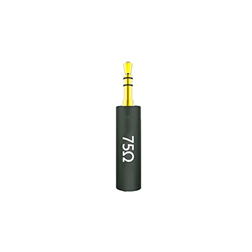
Avoid “impedance adapter” cables that are nothing more than a 75 Ω or 120 Ω series resistor. These were designed to tame excessive output from professional gear and are actively harmful for tonality — they raise effective source impedance by an order of magnitude, which is precisely the condition this guide exists to eliminate.
Pairings That Work — and Pairings That Do Not
We analyzed common source archetypes against the four transducer classes. The patterns are consistent and predictable from the math above.
| Source Archetype | Typical Zout | Typical Vrms | Works Well With | Fails With |
|---|---|---|---|---|
| Modern USB-C dongle DAC | 0.3–1 Ω | 1–2 V | IEMs, 32–80 Ω over-ears | 300–600 Ω dynamics (voltage short), demanding planars (current short) |
| Legacy smartphone / laptop jack | 2–10 Ω | 0.5–1 V | Casual 32 Ω use only | Multi-BA IEMs (tonality error), all high-Z and planar loads |
| Pro audio interface headphone out | 10–40 Ω | 3–7 V | High-Z dynamics (250–600 Ω) | IEMs and low-Z loads — severe response error plus audible hiss |
| Desktop op-amp headphone amp | < 1 Ω | 4–8 V | Nearly everything, including high-Z dynamics | Only the most current-hungry planars |
| OTL tube amplifier | 20–120 Ω | 8–20 V | 300–600 Ω dynamics — the intended application | All low-Z loads; IEMs and planars are a genuine mismatch, not a taste preference |
| Vintage receiver headphone jack | 120–680 Ω | Varies | Period-correct 600 Ω headphones | Essentially all modern headphones |
The OTL tube case deserves clarification, because it is frequently cited as a counterexample to the 1/8 rule. An output-transformerless tube amplifier typically has Zout between 20 Ω and 120 Ω. Paired with a 300 Ω headphone, that yields DF between 2.5 and 15 — often violating the rule. It works acceptably because high-impedance dynamic headphones generally have a flatter relative impedance curve (the resonance peak is a smaller multiple of nominal), so the resulting response error stays modest. Run the Step 4 calculation with your specific headphone’s impedance curve rather than assuming the pairing is either fine or ruined.
Preventative Maintenance & Long-Term Reliability Protocols
Impedance matching degrades over time through contact resistance, not component drift. Series resistance accumulating in the signal path raises effective source impedance and reintroduces errors in a system that previously measured clean.
- Quarterly — contact resistance check. Measure DCR at the headphone plug and compare against your Step 2 baseline. An increase exceeding 0.5 Ω, or a new L/R delta above 1%, indicates oxidation or a developing cable fault. Clean contacts with 99% isopropyl alcohol and a lint-free swab; never use abrasives on plated connectors.
- Quarterly — jack mechanical inspection. Headphone jacks wear mechanically. Insert and rotate the plug slowly while a tone plays; any crackle, dropout, or level change indicates worn spring contacts. On desktop units, intermittent contact can also momentarily open the load, which stresses the output stage.
- Semi-annually — adapter chain audit. Each 3.5-to-6.35 mm adapter, extension cable, and splitter adds series resistance. Count them. For critical IEM listening, keep total series resistance below 0.3 Ω, which effectively means no more than one high-quality adapter in the chain.
- Annually — repeat the Step 3 dual-load measurement. Electrolytic capacitors in coupling-capacitor output stages degrade with age and can raise low-frequency output impedance substantially even when the 1 kHz figure looks normal. If the amplifier uses output coupling capacitors, measure at 40 Hz as well as 1 kHz; a 40 Hz Zout more than 2× the 1 kHz value indicates capacitor degradation.
- Annually — thermal verification on desktop amplifiers. Run a sustained 1 kHz tone into the rated load at 50% of maximum output for 20 minutes. Heatsink temperature should stabilize below 60 °C. Rising temperature with no plateau indicates a bias drift condition that will degrade distortion performance and eventually damage the output devices.
- Operational habit — always power the amplifier on with volume at minimum and allow 30–60 seconds for DC servo and relay protection circuits to settle before connecting headphones. Turn-on transients delivered into a low-impedance planar can exceed the driver’s mechanical excursion limit.
- Documentation — maintain a pairing log. Record Zout, measured DCR, and calculated DF for every source/headphone combination in your rotation. This converts future purchase decisions from subjective speculation into a tolerance check that takes under a minute.
Frequently Asked Questions
Does a higher damping factor always produce better sound in headphones?
No. Beyond roughly DF = 20, further increases are inaudible for any transducer type. The benefit of low output impedance is entirely in flattening the voltage-divider-induced frequency response error, and that error asymptotically approaches zero. Going from DF = 8 to DF = 30 might reduce worst-case error from 1 dB to 0.25 dB — a real but marginal improvement. Going from DF = 30 to DF = 1000 changes the error from 0.25 dB to 0.008 dB, which is physically meaningless. Marketing claims built around four-digit damping factors describe a specification that stopped mattering several orders of magnitude earlier. Prioritize noise floor, voltage swing, and current capability instead.
Why do my planar magnetic headphones sound weak on a dongle with excellent output impedance?
Because output impedance is the wrong specification for that load. Planar drivers present a nearly purely resistive, frequency-flat impedance, so damping factor has essentially no tonal effect. The failure mode is current delivery. A 14 Ω planar at 94 dB/V requires roughly 6.3 Vrms and 450 mArms for 110 dB peaks. A typical dongle delivers 2 Vrms and perhaps 50–80 mA before its supply rail collapses. The symptom is dynamic compression — the sound goes loud but refuses to get big, with flattened transients and a collapsed soundstage. Check the amplifier’s rated output power at your headphone’s specific impedance, not just its maximum voltage. For detailed technical setup and system integration, reference our analysis on wire 4.4mm pentaconn balanced headphone cables (2026).
My amplifier lists output impedance as “less than 0.1 Ω” but my IEMs still sound tonally wrong. What am I missing?
Check three things in order. First, the full series path: the specification applies at the jack, but an adapter, long extension, or thin aftermarket cable can add 0.5–2 Ω, dominating the amplifier’s contribution. Measure DCR of the complete chain. Second, the specification’s test frequency — many manufacturers publish Zout at 1 kHz only, while amplifiers with output coupling capacitors can show dramatically higher impedance below 100 Hz. Repeat the Step 3 measurement at 40 Hz. Third, consider that the headphone may simply have the tonal signature it has. Once Zout is below 1 Ω against a 16 Ω IEM, the calculated response error is under 0.1 dB — at that point the amplifier is no longer the variable, and further source changes will not alter what you hear.